- 您现在的位置:买卖IC网 > Sheet目录871 > OKL-T/3-W5N-C (Murata Power Solutions Inc)CONV DC/DC 9.9W 3A 5VIN SMD
�� �
�
�OKL-T/3-W5� Series�
�Programmable� Output� 3-Amp� i� LGA� SMT� PoLs�
�Output� Current� Limiting�
�Current� limiting� inception� is� de?ned� as� the� point� at� which� full� power� falls�
�below� the� rated� tolerance.� See� the� Performance/Functional� Speci?ca-�
�tions.� Note� particularly� that� the� output� current� may� brie?y� rise� above� its�
�rated� value� in� normal� operation� as� long� as� the� average� output� power� is�
�not� exceeded.� This� enhances� reliability� and� continued� operation� of� your�
�application.� If� the� output� current� is� too� high,� the� converter� will� enter� the�
�short� circuit� condition.�
�Output� Short� Circuit� Condition�
�When� a� converter� is� in� current-limit� mode,� the� output� voltage� will� drop�
�as� the� output� current� demand� increases.� If� the� output� voltage� drops� too�
�low� (approximately� 98%� of� nominal� output� voltage� for� most� models),� the�
�magnetically� coupled� voltage� used� to� develop� primary� side� voltages� will�
�also� drop,� thereby� shutting� down� the� PWM� controller.� Following� a� time-out�
�period,� the� PWM� will� restart,� causing� the� output� voltage� to� begin� ramping�
�up� to� its� appropriate� value.� If� the� short-circuit� condition� persists,� another�
�shutdown� cycle� will� initiate.� This� rapid� on/off� cycling� is� called� “hiccup�
�mode”.� The� hiccup� cycling� reduces� the� average� output� current,� thereby�
�preventing� excessive� internal� temperatures� and/or� component� damage.� A�
�short� circuit� can� be� tolerated� inde?nitely.�
�Output� Capacitive� Load�
�These� converters� do� not� require� external� capacitance� added� to� achieve�
�rated� speci?cations.� Users� should� only� consider� adding� capacitance� to�
�reduce� switching� noise� and/or� to� handle� spike� current� load� steps.� Install�
�only� enough� capacitance� to� achieve� noise� objectives.� Excess� external�
�capacitance� may� cause� regulation� problems,� degraded� transient� response�
�and� possible� oscillation� or� instability.�
�The� “hiccup”� system� differs� from� older� latching� short� circuit� systems�
�because� you� do� not� have� to� power� down� the� converter� to� make� it� restart.�
�The� system� will� automatically� restore� operation� as� soon� as� the� short� circuit�
�condition� is� removed.�
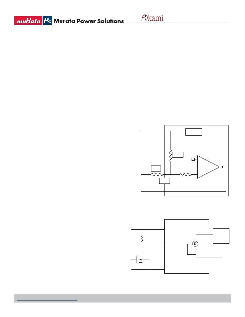
�Remote� On/Off� Control�
�The� OKL� Series� power� modules� can� be� speci?ed� with� either� a� positive� or� nega-�
�tive� logic� type.� See� Figures� 7� and� 8� for� On/Off� circuit� control.� In� the� positive� logic�
�on/off� option� the� unit� turns� on� during� a� logic� high� on� the� On/Off� pin� and� turns� off�
�+Vin�
�R1�
�470K�
�OKL� -T�
�+�
�OUT�
�during� a� logic� low.� In� a� negative� logic� on/off� option,� the� unit� turns� off� during� logic�
�high� and� on� during� logic� low.� The� On/Off� signal� should� always� be� reference� to�
�ground.� For� positive� or� negative� option,� leaving� then� On/Off� pin� disconnected�
�SEQ�
�Control� Voltage�
�SEQ�
�10K�
�–�
�will� turn� the� unit� on� when� input� voltage� is� present.�
�Positive—Units� are� enabled� when� the� on/off� pin� is� left� open� or� is� pulled�
�high� to� +Vin.� The� On/Off� circuit� control� is� shown� in� ?gure� 7.� When� the�
�external� transistor� Q1� is� in� the� off� state,� the� internal� PWM� enable� pin� is� pull�
�high� causing� the� unit� to� turn� on.� When� Q1� is� turn� on,� the� On/Off� pin� is� pulled�
�low� and� the� units� is� off.� Rp� should� be� around� 20K� ohms.�
�Negative—Units� are� enabled� when� the� ON/Off� is� open� or� brought� to�
�GND�
�Figure� 6.� Sequencing� Signal� Interface� of� Module�
�OKL� N� Module�
�within� a� low� voltage� (see� speci?cations)� with� respect� to� –Vin.� The� unit� is� off�
�when� the� ON/Off� is� pulled� high� with� respect� to� –Vin� (see� speci?cations).� The�
�On/Off� circuitry� is� shown� in� ?gure� 8.� The� On/Off� pin� should� be� pulled� high�
�with� an� external� pull-up� resistor� (20K� ohms).� When� Q1� is� in� the� off� state,�
�the� On/Off� pin� is� pulled� high,� transistor� Q3� is� turn� on� and� the� unit� is� off.� To�
�+Vin�
�Rp�
�+Vin�
�On/Off�
�Q3�
�E�
�PWM�
�GND�
�turn� on� the� unit,� Q1� is� turn� on,� pulling� the� On/Off� pin� low� and� turning� Q3� off�
�resulting� on� the� unit� being� on.�
�Dynamic� control� of� the� On/Off� function� should� be� able� to� sink� the� speci-�
�?ed� signal� current� when� brought� low� and� withstand� appropriate� voltage�
�Q1�
�when� brought� high.� Be� aware� too� that� there� is� a� ?nite� time� in� milliseconds�
�(see� speci?cations)� between� the� time� of� On/Off� Control� activation� and�
�stable,� regulated� output.� This� time� will� vary� slightly� with� output� load� type�
�and� current� and� input� conditions.�
�GND�
�GND�
�BOM� ?� Rp� ?� 20K�
�BOM� ?� Q1� ?� Q� SMT� MOS� P� 30V�
�Figure� 7.� On/Off� Circuit� Control� for� Using� Negative� On/Off� Logic�
�www.murata-ps.com/support�
�MDC_OKL-T/3-W5� Series.B01� Page� 15� of� 17�
�发布紧急采购,3分钟左右您将得到回复。
相关PDF资料
OKL-T/6-W12N-C
CONV DC/DC 30W 6A 12VIN SMD
OKL-T/6-W5N-C
CONV DC/DC 19.8W 6A 5VIN SMD
OKR-T/10-W12-C
CONV DC/DC 10A 12VIN POL SIP
OKR-T/3-W12-C
CONV DC/DC 15W 12VIN SIP
OKR-T/6-W12-C
CONV DC/DC 6A 12VIN POL SIP
OKX-T/3-D12N-C
DC-DC CONVRT 0.7525-5.5V 3A 5SIP
OKX-T/3-W5P-C
DC-DC CONVRT 0.7525-3.6V 3A 5SIP
OKX-T/5-D12P-C
DC-DC CONVRT 0.7525-5.5V 5A 5SIP
相关代理商/技术参数
OKL-T/3-W5P-C
功能描述:DC/DC转换器 5Vin 0.6-3.63Vout 3A 9.9W Pos Polarity
RoHS:否 制造商:Murata 产品: 输出功率: 输入电压范围:3.6 V to 5.5 V 输入电压(标称): 输出端数量:1 输出电压(通道 1):3.3 V 输出电流(通道 1):600 mA 输出电压(通道 2): 输出电流(通道 2): 安装风格:SMD/SMT 封装 / 箱体尺寸:
OKL-T/6-W12N-C
功能描述:DC/DC转换器 12Vin .59-5.5Vout 6A 30W Neg Polarity
RoHS:否 制造商:Murata 产品: 输出功率: 输入电压范围:3.6 V to 5.5 V 输入电压(标称): 输出端数量:1 输出电压(通道 1):3.3 V 输出电流(通道 1):600 mA 输出电压(通道 2): 输出电流(通道 2): 安装风格:SMD/SMT 封装 / 箱体尺寸:
OKL-T/6-W12N-C
制造商:Murata Power Solutions 功能描述:DC/DC Converter
OKL-T/6-W12P-C
功能描述:DC/DC转换器 12Vin .59-5.5Vout 6A 30W Pos Polarity
RoHS:否 制造商:Murata 产品: 输出功率: 输入电压范围:3.6 V to 5.5 V 输入电压(标称): 输出端数量:1 输出电压(通道 1):3.3 V 输出电流(通道 1):600 mA 输出电压(通道 2): 输出电流(通道 2): 安装风格:SMD/SMT 封装 / 箱体尺寸:
OKL-T/6-W5
制造商:MURATA 制造商全称:Murata Manufacturing Co., Ltd. 功能描述:Programmable Output 6-Amp iLGA SMT PoLs
OKL-T/6-W5N-C
功能描述:DC/DC转换器 5Vin 0.6-3.3Vout 6A 19.8W Neg Polarity
RoHS:否 制造商:Murata 产品: 输出功率: 输入电压范围:3.6 V to 5.5 V 输入电压(标称): 输出端数量:1 输出电压(通道 1):3.3 V 输出电流(通道 1):600 mA 输出电压(通道 2): 输出电流(通道 2): 安装风格:SMD/SMT 封装 / 箱体尺寸:
OKL-T/6-W5P-C
功能描述:DC/DC转换器 5Vin 0.6-3.3Vout 6A 19.8W Pos Polarity
RoHS:否 制造商:Murata 产品: 输出功率: 输入电压范围:3.6 V to 5.5 V 输入电压(标称): 输出端数量:1 输出电压(通道 1):3.3 V 输出电流(通道 1):600 mA 输出电压(通道 2): 输出电流(通道 2): 安装风格:SMD/SMT 封装 / 箱体尺寸:
OKL-T1-W12
制造商:MURATA-PS 制造商全称:Murata Power Solutions Inc. 功能描述:Programmable Output 1-Amp iLGA SMT PoLs